Cais′son.
1. A carriage accompanying a fieldpiece to carry ammunition, and participating with it in its maneuvers, forming in line in the rear of its piece when the latter is in action.
The name
caisson is also applied to an ammunition-chest.
See gun-carriage.
2. A water-tight structure or bag placed beneath a sunken vessel, and then either supplied with air by pumping out the water and allowing air to enter, or distended by air from an air-pump, so as to assist in floating the vessel.
3. A water-tight box or casing used in founding and building structures in water too deep for the coffer-dam; such as piers of bridges, quays, etc.
The caissons employed in building the piers of the railroad bridge over the
Susquehanna at
Havre de Grace, Md., are an example of the use in the first-mentioned capacity.
Caissons resting upon a river-bed subject to washing have proved to be unsafe, as was evinced at Westminster Bridge, where the caisson was undermined by the current; the structure was saved by sheetpiling and underpinning.
The plan adopted by Peronnet and other eminent French architects was to drive a substratum of piles, which were sawn off to a level surface, forming a foundation for the structure which settled the caisson on its bed of piles as the masonry progressed.
For the purpose of securing the coincidence of the caisson and its bed of piles, one of the latter was allowed to project upwardly, as high as the top of the caisson, occupying a well or water-tight curb which was open at each end. The long pile formed a guide, causing the caisson to settle correctly into position.
The guide-pile has been occasionally used, but is by no means a necessary feature of the work.
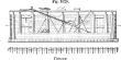
When the work is concluded, the sides of the caisson are knocked away, leaving the pier in position, as shown in the illustration.
[
421]
a represents the sinking of the caisson.
b, the pier on its foundation.
The caissons used by De Cessart in 1757 for the piers of the bridge at
Saumur were sunk upon a foundation of piles, the heads of which were previously cut off to a level of about six feet below the water-surface.
Each caisson was 48 × 20 feet, the ends being pointed and the sides removable, so that they could be used with another bottom after the masonry was laid nearly to the water-line.
The bottom had a floor of lower beams laid side by side, and planks 14 inches thick, and the frame timbers were rabbeted to receive the uprights of the sides, which were secured to the bottom framing by dovetails and wedges, so that, the latter being withdrawn, the sides were disconnected.
The sides were 16 feet high, of scantling laid on edge and maintained in position by uprights, secured by struts and overhead braces, so as to resist the pressure of the water, and also by lap-joints and uprights at the angles of the caisson, the whole carefully calked.
The caisson was built on the bank of the river upon piles cut to three different hights above the water; by blocking up, its bottom was kept level while building, and by removing these blocks, and with the aid of jacks, it was tilted so as to slide readily into the water, when it was towed into position, and the masonry laid until it sunk squarely on the heads of the piles previously driven for its reception.
 |
|
Caissan. |
The modern or pneumatic caisson, which is sunk through quicksands or submerged earth or rock, is the invention of
M. Triger, who contrived by the aid of air-pumps to keep the water expelled from the
sheet-iron cylinders, which he sunk through quick sands in reaching the coal-measures in the vicinity of the river
Loire, in France.
The seams of coal in this district of
France lie under a stratum of quicksand from 58 to 66 feet thick, and they had been found to be inaccessible by all the ordinary modes of mining previously practiced.
Fig. 1021 illustrates the caisson of
M. Triger, and shows the comparatively simple form which the apparatus assumed when used for sinking a simple shaft through a water-bearing stratum above the coal.
Air is forced in through the pipe
A to the working-chamber
B, which has a man-hole in the floor above.
C is the middle chamber, which has also a man-hole in its ceiling.
D is a pipe by which sand and water are ejected from chamber
B, under the pressure of the condensed air in the latter.
The pressure of air in chamber
B being such as to exclude the water, the workman descends through the man-hole in the floor of chamber
E and closes the door behind him. Admitting air from chamber
B until the pressure is equal in the two, be opens the door in the floor of chamber
C and descends to his work.
The buckets are similarly managed, the middle chamber
C, acting as the means of communication, being filled with air at normal pressure, or with compressed air, according as it is in communication with the open air of chamber
E or the condensed air of chamber
B. The device which thus acts as an intermediate is termed an air-lock, and is the notable point of invention in the apparatus.
 |
|
Teiger's caisson. |
The cast-iron piles which support the arched bridge over the
Medway at
Rochester, England, were sunk by the means of compressed air, which kept them empty of water while workmen excavated the materials inside the piles.
Each pier consists of fourteen cast-iron cylinders placed in a double row, and sunk through the bed of the river into the hard chalk.
This plan is the reverse of
Pott's mode of sinking cylinders, in which the air is withdrawn from the interior so as to utilize the pressure of the atmosphere in forcing the pile downward, while the material, of a somewhat soft nature, ascended into the cylinder.
The contents were from time to time scooped out, and the air-exhausting process repeated.
This plan was adopted with a bridge which crosses the
Thames near
Richmond, England.
Fig. 1022 is a section of the movable iron caisson used in building the piers of a bridge at
Copenhagen, Denmark.
It comprises an upper chamber communicating with the air, an intermediate or airchamber, both equal and cylindrical in section, and a
[
422]
lower working-chamber of larger section than the foregoing, and adapted to the shape of the pier; the whole raised or lowered by suspension-chains, and ballasted with iron and water contained in two annular chambers
A and
B, surrounding the lower part of the air-lock.
In working, the apparatus was lowered to the bottom of the water, and an excavation made until a stratum capable of forming a solid foundation was reached; upon this a layer of concrete was laid, and then the structure completed with brick-work faced with granite; the caisson was gradually raised as this progressed, and when it was finished up to the water-line, the caisson with its suspending stage and tackling was removed to the site designed for another pier, where a similar operation was repeated.
Caissons of this kind, having an open bottom and provided with air-locks, act upon the principle of the diving-bell, the pressure of air in the working chamber and air-locks being equal to that of the depth of water in which they are submerged.
This renders the use of the air-lock necessary.
The piers of the
Illinois and
St. Louis Railwaybridge, across the
Mississippi, at
St. Louis, are constructed by means of an analogous device.
See Airlock, opp. p. 49.
These, however, are not designed to be removable.
The matter to be excavated, being principally sand, is brought up by sand-pumps with extension suctionpipes.
A hose, connected with a force-pump, is employed to reduce this matter to a proper consistency.
When solid rock is reached, the air-chamber, locks, and shafts are filled with concrete to the top of the pier, which has been gradually built up on the roof of the air-chamber, and around the caisson, as the sinking of the latter proceeded.
The caisson designed to find a stable surface and establish the foundation of the pier for the
East River Bridge, between New York and
Brooklyn, is rectangular; in length, 168 feet; width, 102 feet; interior hight, 9 1/2 feet, with a roof 5 feet thick; the sides are 9 feet thick at the roof, sloping down to a round edge, so as to facilitate its entry into the ground.
This part is of cast-iron, protected by boiler-plate; the remainder, of heavy timbers strongly bolted, braced, and specially coated to prevent leakage of air or water through the pores and joints.
It is provided with air-shafts and locks, and air-supply shafts for the chambers, and also two water-chambers, into which materials excavated by the workmen are placed, and elevated by a peculiar dredge.
4. A sunk panel in a ceiling.
See coffer.
5. A chest filled with explosive material, laid in or beneath the track or expected position of an enemy.


