Tube.
1. A metallic pipe, of many kinds and uses.
 |
|
T-square. |
The first wrought-iron tubes made on a large scale were for barrels of fire-arms (see gun-barrel), but the introduction of illuminating gas, in the first place, found a use for the old musket-barrels which were stored away after the
general peace of
Europe, 1816, and subsequently gave rise to a general demand for tubing of various lengths and sizes, for which the old barrels would have been unsuited had they not already been exhausted.
Under
Russell's patent, 1824 (
English), the tubes were first bent up by hand-hammers and swages, to bring the edges near together, and then they were welded between semicircular swages, fixed respectively in the anvil and the face of a small tilt-hammer worked by machinery, by a series of blows along the tube, either with or without a mandrel.
The tube was completed by being passed between rollers, with half-round grooves, which forced it over a conical or egg-shaped piece at the end of a long bar, to perfect the interior surface.
Various improvements were afterward made, as, for instance, bending the skelps, first to the semi-cylindrical and then to the tubular form, preparatory to welding, by swage tools, worked by machinery.
The whole process was afterward carried on by rollers, which were abandoned on account of the difference in velocity between the greatest and least circumferences of the rollers.
Subsequently, the plan was adopted of bending the end of the skelp to the circular form, and heating the whole skelp to a welding heat in a furnace.
It is then dragged by the chain of a draw-bench through a pair of tongs, with bell-mouthed jaws, which are opened at the moment of introducing the skelp.
No mandrel is employed.
By this means wrought-iron tubes, from 1/4 inch diameter and 1 10 inch bore up to those of 6 inches internal diameter and 1/9 to 3/8 inches thick, are made with a perfect weld.
[
2641]
The following table shows the progress of invention in this direction: —
| Draw-bench introduced into England | 1565 |
| Rolls invented for rolling iron, by Henry Cort | 1783 |
| Draw-bench and rolls used for making lead-pipe, by Wilkinson | 1790 |
| Combination of 2, 3, or more pairs of rolls, by Hayledine | 1798 |
 |
|
Principles of action of tube-making. |
Welding.
a, hand-hammer.
b, power-hammer.
c, rolls with several passes.
d, alternating holes.
e, segment moving on a bed.
f, three or four rolls making one hole.
g, drawing through holes or tongs.
h, drawing through rolls.
Finishing.
i, draw-bench and rolls.
j, draw-bench and rolls.
Drawing over a Mandrel.
k, no mandrel.
l, parallel and in motion.
m, taper and in motion.
n, enlarged end and at rest.
Form of Joint.
o, but or jump.
p, scarf or lap.
The excellence attained in making tubes has been owing to the persistent attempts at perfection in manufacturing two articles, — gun-barrels, and tubes for steam-engine boilers and condensers.
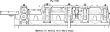
The series of English patents on this subject may be thus enumerated, — the letters in parentheses have reference to the diagram,
Fig. 6718: —
Cook, 1808 (
a i j l p) 1.
Forge a round bar, drill a hole longitudinally; elongate by draw-plates, or grooved rollers, over a mandrel.
2. Turn a skelp over a mandrel; weld, and draw as before.
3. Force a circular plate of iron through a series of holes in a die, giving it a cup-shape, which is eventually opened at bottom and elongated to a cylinder, by drawing as before.
James and
Jones, 1811 (
b c m p). 1.
The heated skelp is turned over a mandrel, and swaged by a hammer, while resting in a grooved anvil.
2. Welded and rolled by grooved rollers.
Osborne, 1817 (
b c d e n p). The skelp is turned and welded on a mandrel, which has a shield to prevent its passing between the rollers, so that the barrel is drawn off the mandrel.
This is repeated with progressively smaller mandrels and grooves.
Russell, 1824 (
b j k l o). The skelp welded by grooved anvil and top tool.
Whitehouse, 1825 (
g k o). The skelp was turned into position for welding, and was then drawn between dies, or passed between grooved rollers, without mandrel or internal support.
Royl, 1831 (
c i k o). Two grooved rollers, which received bent and heated skelp, and drew it out of the mouth of the furnace.
Harvey and
Brown, 1836 (
c n o p). The mandrel was a short instrument, just in front of the rollers, so that the enlarged head came just beyond the pinch of the rollers.
In working, the heated tube was forced over the short, cranked stem of the mandrel, the unclosed seam of the tube being sufficiently open to allow it to pass the fin by which the stem of the mandrel was carried.
Russell, 1836 (
h i j k o). The end of the skelp being turned around, so as to make the edges lap, it is pulled at a welding heat between dies, or rollers, without a mandrel or central support.
Prosser, 1840 (
f n o p). Four rollers, each having a groove equal to the quarter of the circumference, and driven by gearing, so as to travel at the same velocity.
The end of the skelp was bent around, entered between the rollers, and discharged on to a straight mandrel, smaller than the bore.
Cutler, 1841 (
g h i k n o p).
Russell Whitehouse, 1842 (
g l p). The skelp, bent into an oval form, was placed on a small mandrel, which filled it across the minor diameter.
The pressure was applied at the other edge of the lap, then at the inner, and lastly in the middle.
Drawing between dies restored the circular form and loosened the mandrel.
Russell, 1845.
The edges of the skelp are lapped on a long bar, which is then drawn beneath a grooved roller, to close the weld.
Banister, 1849.
Has a combination tube, brass inside, then iron, copper outside, so that the former is exposed to the fire, the copper to the water, and the iron stiffens both.
The annealed tubes, of proper size, are telescoped, and then drawn between dies, to elongate and attenuate them.
Ostrander's tubular iron is rolled with a compound mandrel, 30 feet long, of required diameter and shape, and with a hole from 1/16″ to any required size.
It is used for stay-bolts for boilers, where it indicates, by leaking into the fire, if the bolthead has given way; also used for hollow pump-plungers, etc.
Fig. 6720 is a machine for making sheet-metal tubes from blanks or skelps.
A series of pairs of rolls is used in connection with a stationary mandrel of peculiar shape, by which the sheet of metal is first bent to the form of a trough, with one edge higher than the other; then into a tube, with its marginal surfaces bent up and in contact.
The projecting edge is next bent over, and, lastly, the lap is bent down upon the tube and flattened.
Telescope-tubes are made of brass skelps, turned over and soldered.
They are then forced on to a steel mandrel and drawn through a die.
Fluted tubes are drawn through ornamental dies of the required form.
The mandrel is frequently cylindrical.
Joint wire is a fine tube used by silversmiths and watch-case makers.
A small pipe is threaded on a piece of steel-wire, and both are drawn through a die, like a piece of solid wire.
See pipe; lead-pipe.
For
lead-pipe making and
lining with tin, see pages 1271, 1272.
For
making of gun-barrels, see pages 1032, 1033.
For
bushing, see page 413.
See also pipe, pages 1707, 1708, and list under that head.
For tubing for oil-wells, see well-tubing.
2. India-rubber tubes are made: —
1. By wrapping slips of rubber or rubbercloth around a mandrel of glass, which is afterward withdrawn, the layers and the edges being joined by solvents or heat.
2. By driving the pastry mass out through an annular die-opening, in the manner of making lead-pipe (which see).
 |
|
Flexible tubing. |
The flexible tube (
Fig. 6719) has a framework of flattened wire, wound spirally round a mandrel.
This tube or coil is then covered with a braided or woven coating saturated with oil or varnish.
Another coating of a narrow strip of leather is then wound spirally over this and oiled or varnished, over which is woven or braided another coat which forms the outside, and which is then oiled or varnished.
The mandrel is then withdrawn from the finished tube.
 |
|
Machine for making sheet-metal tubes. |
3. (
Ordnance.) A primer for ordnance.
A small cylinder placed in the
[
2642]
vent of a gun, and containing a rapidly burning composition, whose ignition fires the powder of the charge.
See priming-tube.
The
friction-primer or
friction-tube is a variety of
priming-tube. See friction-Primer.
4. (
Hydraulics.) The barrel of a chain-pump.
5. (
Steam.) A pipe for water or fire in a steamboiler.
It would be well to call water-pipes
tubes, and fire-pipes
flues, if it were not too late to attempt careful nomenclature now. The present practice is to call them flues or tubes, according to their relatively large or small diameter respectively.
See tubular boiler.
Tubes, in locomotive-boilers, are of brass or iron, about two inches outside diameter.
They extend between the tube-sheets of the boiler, and are fixed in them by ferrules driven in at each end, which make them steam-tight.
6. (
Surgical.)
a. An esophageal tube, capable of being passed into the stomach.
b. An elastic gum tube passed
per ano into the colon, to discharge air or introduce enema.
c. A tracheal tube.
 |
|
Tube-brush. |


