Wa′ter-me′ter.
A device for measuring the amount of water received or discharged through an orifice.
Water-meters may be divided into seven classes:—
1. Those in which the water is passed through a horizontally rotating case having a peripheral discharge, or fixed case containing a horizontal wheel with spiral flanges, like a turbine, and delivering a known amount at each rotation.
2. A piston or wheel with vanes or buckets rotating in a chamber and operated by the pressure of the water.
These act on the principle of the rotary steam-engine, and are the converse of the rotary pump, in which the
rotating piston drives the water.
3. The Archimedean screw rotating in a tube.
4. A piston reciprocating in a cylinder of known capacity.
This acts on the principle of the ordinary steam-engine, in which the steam drives the piston, and is the converse of the ordinary force-pump, in which the piston drives the water.
5. The
meter-wheel.
6. The pulsating diaphragm, which displaces the water from its respective sides alternately, and is the converse of the old
Cracknell pump (
English).
7. The bucket and balance-beam, in which the reservoirs of known capacity on the respective ends of the beam are alternately presented to catch the water, and are depressed and emptied as they become filled.
Whichever of these principles be adopted, the number of oscillations, reciprocations, or rotations, each of which permits a definite quantity of the fluid to pass through the meter, must be registered by appropriate mechanism.
This may be variously modified, but, in general, a shaft caused to have continuous rotation in one direction is employed to set in motion a train of gearing which moves a series of indexes that point out on their appropriate dials the quantity of fluid delivered.
See gas-meter; liquid-meter; spirit-meter.
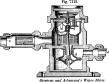
Class 1.
Siemens and
Adamson's meter acts on the principle of
Barker's mill.
The water is conveyed by a tube
a to a horizontal drum
d, rotating on a vertical shaft
c, having at its upper end a worm which communicates motion to the registering gearing.
The drum has three or more tangential apertures at its periphery, and discharges a given amount of water at each revolution, which is carried away by the pipe
e. b f are gratings to arrest impurities.
See also Fig 2970,
A, page 1327.
Class 2.
In
Turner's meter (
Fig. 7111), water admitted through the pipe
G enters alternately into the hollow rotary piston
E through the openings
E2 E3, and passing behind the pivoted wing-pistons
H H, causes continuous motion in one
[
2741]
direction.
The water entering the chambers
E1
Eix is discharged as each port arrives at the eduction opening.
The wing-pistons also act as valves, and each is closed in so as to become inoperative by striking against the abutment
I.
 |
|
Turner's rotary piston water-meter. |
Summer's (
Fig. 7112) has a rotary disk
B journaled eccentrically in the case
A, which has a shallow, lunate cavity at its upper side, concentric with the disk, to give longer packing surface to the pivoted wings
e, which bear against the side all around.
See also Figs, 2970,
C; 2971, pages 1327, 1328.
See also rotary pump,
Figs. 4465,
4466; rotary meter, Fig. 4461; rotary steam-engine, Plate LIII., page 1990, etc.
 |
|
Sunmer's rotary piston water-meter. |
Class 3.
Maxim's meter (
Fig. 7113) is of the screwshaft class.
The liquid entering through the opening
a is received in a chamber
b, flows downward through the square trunk
e, and is discharged at
d. The trunk
c has a vertical inwardly projecting web at each angle, just cleared by the wings of the screw, and preventing the water from acquiring a rotary motion.
A casing
d prevents the water from causing a lateral displacement of the screw-shaft.
The shaft
e is hollow, and is made slightly more buoyant than water, so that when a small quantity only is flowing, the shaft will be buoyed up and turn upon its upper pivot, which is made sharp and delicate, so that the resistance is reduced to a minimum; but when a larger quantity of water is passing, the shaft is depressed, and turns on its lower and larger bearing.
Bicarbonate or supercarbonate of soda and dry tartaric acid are placed in the shaft, so that in case of water sweating through, a combination ensues, causing the evolution of a gas which resists the farther entrance of water and maintains the buoyancy of the shaft.
 |
|
Maxim's Archimedean-screw water-meter. |
A train of gearing in the chamber
f communicates, through the medium of a crank and arm connection
g, rotary motion to a shaft passing through a water-tight plug and actuating the indicating mechanism.
See also Fig 2972, page 1328.
Class 4.
The
reciprocating piston.
Worthington's doublepiston meter ( “Pioneer” ) has two parallel cylinders, in each of which are two pistons connected by a stem and acting together as a double piston.
The space between the pistons is greater than the stroke, is filled with water, and contains the mechanism which actuates the valves.
Under the central space of each set of pistons is placed the slide-valve of the other set, so that each piston in its motion actuates the valve to admit water against the other piston, the action being reciprocal.
A somewhat different construction, which has its analogue in many modern
steam-engines and steam-pumps, is that in which two pistons and two valves or sets of valves are employed.
One piston is smaller than the other, and operates in a cylinder connected by a port with the larger cylinder.
The duty of the smaller piston is to operate the valve of the larger one.
The larger piston in its motion actuates a small valve, admitting water to the smaller cylinder; the pressure of water in the latter operates the smaller piston, and this actuates the main valve.
Somewhat similar is the construction adopted by the
Hudson Brothers in their steam-pump, and it likewise is applicable to liquid meters.
The larger piston in its motion uncovers a port leading to the smaller cylinder; the pressure of water in the latter actuates the small piston, and this moves the valve.
But one valve is thus used at each end of the double-acting apparatus.
The valve-apparatus of
R. C. M. Lovell's steamquarry-ing machine is thus constructed.
George I. Washburn's engines, whose construction adapts them to be used as meters, are suggested by the foregoing remarks on the Worthington meter.
In
Washburn's, two pistonstems are used, reciprocating in their several cylinders, and each having a plurality of disks.
Though his numerous engines vary in details, the feature of a plurality of disks on pistons reciprocating in separate cylinders is preserved.
In most of his engines, the piston of each cylinder is alternately a working piston and a valve, each governing the admission and exit of steam (or water) to the other cylinder, reciprocally.
In some other of his engines, the valve-stem is connected by a
reach to the working piston.
As it is not desirable to duplicate cuts in a work where they are necessarily so numerous, we refer the reader to steam-engine, where the above and other
steam-engines capable of adaptation as water-meters will be found described.
It is, however, proper to remark in this connection, that this feature of making one reciprocating piston act as a valve to another similarly moving piston is found in the old and the new steamhammer.
The main piston in its descent, for instance, uncovers a port which admits steam to a piston-valve, whereby the steam induction is accomplished.
See also piston-valve.
The Jopling meter (
English) consists of “two short, doubleacting cylinders and pistons, each cylinder supplied at the side with a common D slide-valve, in appearance precisely like two steam-engine cylinders with usual pistons and slide-valves, with the only difference that the port in one of the latter is reversed.
These cylinders are so placed opposite each other that the pistonrod of the one at the end of its stroke can move the valve of the other on the ‘tappet’ mode, and
vice versa. The whole is surrounded by a strong casing full of the water to be measured.
The mode of operation is similar to that of
Worthington's meter, with the exception that the pistons have no dead-water to carry with them.
The piston-rods, however, pass through stuffingboxes, which in the Worthington meter is avoided.”
See also
Fig. 2974, page 1328.
The
Hicks meter is adapted from his ingenious steam-engine, in which the cylinders are situated radially around a central space occupied by the common crank, to which their pistonrods are attached.
The piston-rods of opposite cylinders, being continuous or practically so, may thus be considered as one, having a piston operating in two opposite cylinders, with a steam (or water) space between them.
The effective strokes of the pistons are made consecutively, each commencing a stroke at each quarterly point in the revolution of the main shaft.
In the meter the main shaft is connected to a register which records the revolutions, each revolution representing on the index (in gallons, for instance) the sum of the capacity of the several cylinders.
No valves of ordinary construction are used, but each cylinder and piston has ports so arranged as to form induction and eduction passages.
Each of the pistons forms an induction-valve for the piston in advance and an eduction-valve for the piston in the rear.
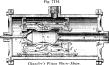
Chandler's meter (
Fig. 7114) is one of the reciprocating-piston class.
The water, entering by the induction-pipe
a, passes through ports
b to the interior of a valve
e, having a reciprocatory motion within the piston, which consists of two heads
d d′ connected by rods
l l; flowing through the ports
f f. it forces the piston away from the head
e of the case toward the bead
e′, the water contained between the latter and the head
d′ of the piston passing through the ports
g g between the valve and the piston to the discharge-opening
h of the meter.
On approaching the
[
2742]
head
e′, the spiral spring
h′ on the rod
i strikes against this head, reversing the movement of the valve by means of a lever
k, one end of which is pivoted in a slot in one of the stays
l and connected with one of two elliptical springs
m having a depression in which a collar
n centrally surrounding the valve rests.
This movement of the valve closes the ports
f f and opens the corresponding ports between the valve and piston, producing a reverse movement of the piston, and causing the water which had accumulated between the heads
d e of the piston and meter to flow between the valve and piston at that end toward the dischargeopening.
 |
|
Piston water-meter. |
The piston-rod
o is connected with suitable mechanism for registering its reciprocations.
Fig. 7115 shows another form of this meter, having a differently arranged spring and rod for causing the throw of the valve, which is cushioned by annular watercham-bers
p p at each end of the piston.
In a third modi fication, the valve is shifted by a weighted forked lever partially embracing it and connected with the sliding rod.
The Despers watermeter has two connected pistons, a valve, and registering-pinion.
In
Spencer's (Fig.
7116), two measuringchambers
f g act alternately to receive and discharge the water The case containing the operating parts is tight, and is so constructed as to form the heads of the cylinders, whereby stuffingboxes are dispensed with The pistons are connected to the cranks of the shaft of the eccentrics, which operate the slide-valves through the medium of connecting-rods
n n See also
Fig. 2974, page 1328.
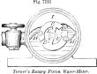
Class 5.
The meter-wheel.
Hargrave's meter (
Fig. 7117) has two chambers
B C which are alternately tilted to be filled with water from the induction-pipe
G G. The water flows in turn through the pipes
f g, the partition
D preventing its being received into the opposite chamber.
When full, it is, by its own gravity, assisted by the weight
H, which
G rolls from side to side on the track
I, tilted until the projecting stem of a valve at its lower angle strikes a stop in the chamber
A, which opens the valve and allows the water to escape into this chamber, whence it passes through opening
l into an air-chamber
J, or direct to the place of delivery.
In the mean time the other chamber is being filled, to be tilted in its turn.
The chambers
B C are balanced on a knife-edge
e, and the induction and eduction cocks are arranged to be simultaneously opened and closed.
See also liquid-meter,
Fig. 2970,
A.
 |
|
Meter-wheel water-meter. |
 |
|
Pulsating-diaphragm water-meter. |
Class 6.
The
pulsating diaphragm.
Baldwin's meter (
Fig. 7118) has an elastic diaphragm dividing it into two chambers, each having an inlet and outlet aperture, the former provided with a valve
n, and the latter having the separate valves
c1
c2.
The diaphragm is centrally attached to a sleeve
o o′ sliding on the rod
s s′, and which, as it moves alternately from side to side through the medium of the levers
z z′, moves the valve
n so as to close one and open the other of the induction-openings.
The same movement operates to open one and close the other of the eduction-openings, a rapid motion being imparted to the rod
s s′ toward the end of each stroke by the arms
x x′, which have friction-rollers on their ends acting against the wipers
r r′, and are actuated by springs
y y. The eduction-passages
h i coalesce in a single pipe.
See also Fig. 2970,
B (two figures).
Class 7.
The
bucket and
balance.
 |
|
Balancing-chamber water-meter. |
Weller's (
Fig. 7119), though adapted for use as a water-meter, is more particularly designed for oil, spirits, etc. It consists of a box or frame
A A, on which are mounted two casks of equal capacity, and rocks upon a central pivot.
Two levers
H H′ are connected by chains
F F to quadrants
G G or their equiva-
[
2743]
lents, which operate to open the induction and close the eduction cock of each cask when it is tilted into elevated position, and
vice versa. When a cask becomes filled, its weight overcomes that of the empty cask and that of a ball
I, which runs in ways, and is then at the depressed end of the box; but as that end rises, the ball rolls toward the other end, and, striking the lever
H at that end, causes it to pull the chain so as to open the eduction and close the induction cock of the lower cask, while opening the induction and closing the eduction cocks of the upper one.
The flexible discharge-tubes
K K belonging to each cask coalesce in a single tube.
An adjusting-ball
B′ is provided for graduating the preponderance of the ends of the box, to adapt the meter for liquids of different gravities.
See also
Fig. 2973.