


A′e-ro-steam En′--gine.
An engine in which the expansive power of combined heated air and steam is used in driving a piston.The Air Engine followed closely in the wake of the Watt Steam-Engine.
Oliver Evans, during the latter portion of the last century, suggested the combination of the heated gases and air with the steam, as a motor. He called it a volcanic engine, which see.
Glazebrook used moistened hot-air in his Air Engine, English Patent, 1797. See air engine.
The air is moistened before reaching the cylinder in Paine's Engine, United States Patent, November 30, 1858. In this case it is the cool refrigerated air that is moistened, and the amount of moisture [21] would be very far below saturation when the air came to be heated.
The same may be said of Glazebrook's, 1797, with the additional remark that Glazebrook condensed the air in the preliminary process, before exposing it to moisture, so that the heat incident to its condensation would enable it to absorb more water, but still far less than would be sufficient to saturate it when it came to be heated by the furnace.
 |
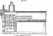
| Bennett's aero-steam engine. |
Bennett, United States Patent, August 3, 1838, introduced, or at least adopted, two new features: 1. He conducts the incoming charge of air to the furnace, and makes it the means of maintaining combustion under pressure; 2. The furnace is air-tight, and the volatic results pass through the steam-boiler, are washed, and pass, fully saturated, to the cylinder. See air engine.
The steam and air might have been combined in any required relative ratio in this boiler, but the inventor does not appear to have supposed any specific proportion was necessary. a a is a vertical cylinder constituting the shell of the boiler, b b a smaller cylinder placed within the former and forming the furnace and ash-pit; this is entirely surrounded by water. c is a tube connected with a blowing-machine, and having two branches d and e, — the former of which admits a portion of air above the fuel, and the latter a portion into the ash-pit below the fire-bars. Two throttle-valves, or dampers, f f, are provided to regulate the draft through each branch, g is a short cylindrical neck, through which the smoke and heated air pass into the steam-chamber, where they mix with the steam, and with it pass to the working cylinders. The neck g is covered with a valve h opening upward, the sides of which are turned down to cause the heated air to pass through the water, and thereby give out a portion of its heat to the latter; this also serves to wash the heated air and arrest grit which would injure the cylinder and piston. i, a safety-valve, k, a valve by which the pipe that conveys the steam to the engine can be closed when required; l, the pipe by which the water is conveyed to the boiler from the feed-pump; the end of this pipe enters the boiler and delivers the water on to the top of the valve h; this is with a view to prevent the valve becoming excessively heated by the action of the fire. m is the fuel-spout by which coal is introduced into the fireplace; on it is bolted the hopper n, having at its upper end a flat sliding valve o, and another one p at its lower end; these valves slide in grooves, and are moved by means of racks and pinions. They are ground to their seats so as to make air-tight joints, and during the whole time the engine is in operation the coal-hopper is kept closed by one or other of these valves. In kindling the fire the valves o and p are both opened, lighted kindling is dropped through the chute, and then a quantity of fuel. The valves are then closed, the blower started. When the engine is set to work, it forces air into the furnace both above and below the fuel at each stroke, which, having no vent to escape but at the valve h, accumulates in the furnace until its pressure somewhat exceeds that of the steam upon the valve h, when it lifts the valve, and, rising up through the water, mixes with the steam, and passes along with it to the engines. t is a slider, by opening which the ashes from the furnace can be withdrawn; when this is requisite the dampers f f must be first closed. v is the blow-off cock, by which the water can be discharged from the boiler when required, and w is a hole covered by a door for removing any mud which may have accumulated. At x is a glass gage to show the height of the water in the boiler, and at y is a glass eyepiece through which the state of the fire can be ascertained. z is the man-hole of the boiler.
 |
| Tanger's steam-generator. |
William Mont, storm's experiments in combined air and steam covered the period 1851-55, and perhaps later. His Cloud Engine, in which steam and air, in a condition resembling fog, were used to propel a piston, was exhibited at the fair of the American Institute, New York, in 1855. The machine appears to have failed to realize the expecta- [22] tions of the inventor. There was a lack of adjustment somewhere, it may be supposed, but the end is not yet.
In Washburn's Air-Heater and Steam-Generator, United States Patent, September 5, 1865, the air is also introduced under pressure into the furnace, and then passed through a cleansing-tank before being added to the steam evolved in the coil of pipe which constitutes the steam-generator. In this apparatus full saturation is obtained. See illustration in air engine.
Stillman's Hot Air and Steam Generator, August 9, 1864, has also the combination of air and steam.
Bickford's Patent, June 6, 1865, may also be examined in this connection.
In Tanger's Steam Generator, December 4, 1866, the air is injected into the pipes E and I by means of a force-pump, and after being heated while passing through the convolutions of the pipes F and J, is forced into the boiler by nipples, as shown at K.
In Tarr's Aero-Steam Engine, 1867, the air is heated within the furnace, and is thence forced through the pipe into the steam-chest, where it mingles with the steam coming through the pipe; and the mixture of steam and hot air is by means of a slide-valve admitted alternately above and below the piston in the ordinary way, so as to produce the usual reciprocating motion.
Warsop's Engine (English), 1869, is started by steam in the ordinary manner. A single-acting airpump, worked from the crank shaft, compresses air to a little more than the boiler pressure; the air then passes through a long circuit of straight and coiled pipe, which traverses the exhaust-pipe, makes several spiral coils in the chimney, then descends at one side of the fire-box, is exposed to the full fire, and finally passes by a valved opening into the boiler at the bottom of the water-space.
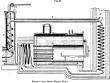 |
| Warsop's aero-steam engine-boiler. |
Warsop's object is similar to that of several of his predecessors, to make steam assist the expansive force of air, and to avoid the difficulties of lubrication incident to the use of hot air alone. He attempts to obtain the maximum effect from mixed air and steam by instituting a certain approved proportion between the two. It is quite probable that such a ratio may be found, and that it may secure substantial economical advantages.
The pipe A, through which the air is forced into the boiler by the action of the air-pump, is of iron, and is 111/16 inches in diameter outside, and 1 1/4 inch bore. On leaving the pump the pipe is first led to the heater B, shown on the left of the engraving, wherein it is exposed to the exhaust steam. The heater consists, as will be seen, of a cast-iron cylindrical vessel placed in a vertical position and provided with two branches — one near the bottom and the other near the top — through which the exhaust steam respectively enters and escapes from the casing. At the top of the heater is placed a small cylindrical tank D, exposed at the bottom and sides to the exhaust steam, and perforated around the upper part of the sides, so that in the event of its receiving an excess of water the latter may overflow and fall to the bottom of the heater. Through a stuffing-box at the bottom of the tank there passes a tube with a rose E at the lower end, this tube being carried by a float F, which swims in the water at the bottom of the heater, as shown, and, by means of a cord passing from the top of the tube, works a cock G, which regulates the supply of water to the tank at the top of the heater.
The air-pipe A, after leaving the heater just described, passes along the exhaust-pipe C to the chimney H, and, descending the latter spirally, as shown, passes into the flue beneath the boiler. Here it is led backward and forward, as shown in the plan, and after making several convolutions in the smoke-box, is led back to the front of the boiler, where it communicates with a valve-box, containing an ordinary, light clack-valve. The object of this valve is to prevent water from entering the airpipe when the engine is stopped. From the valvebox a pipe is led down within the boiler to the bottom of the latter, this pipe being perforated at intervals on the upper side. The perforations are placed closer together at the farther end of the pipe than they are at the end at which the air enters, and by this means an equable distribution of the air at the different parts of the boiler is insured.
The lengths of the various portions of the airpipe are as follows: In feedwater heater, 12 feet; in exhaustpipe, 13 feet 6 inches; in chimney and flues, including coils in smoke-box and under boiler, 58 feet; total, 83 feet 6 inches. The total external surface exposed by this pipe is thus about 36 3/4 square feet.
The principal dimensions of the [23] boiler are as follows: Length, 8 feet; diameter of shell, 3 feet 6 inches; diameter of fire-box flue, 2 feet 2 inches; length of fire-box and combustionchamber, 5 feet; and length of tubes, 3 feet. The tubes are 41 in number, most of them being 2 5/8 inches, and some of them 2 5/16 inches diameter. The total effective heating surface exposed by the boiler is about 130 square feet.
