Roll′ing-mill.
In the rolling-mill, the iron, which is heated and balled in the puddling-furnace, is made into bars or sheets.
The rolls are journaled in pairs in metallic boxes in the iron standards or cheeks, and are capable of being set toward or from each other by means of set-screws.
The grooves in the rolls are so made as to be coactive in giving the required form to the heated iron passing between them.
Sometimes, as in the larger description of rolls, the grooves are counterparts, each forming one half of the bar of iron; and sometimes a ridge or rib on one roll projects into a groove in the roll beneath and forms one side only of the bar. The face of each roll has a series of grooves gradually decreasing in size toward one end. The iron is passed through each in succession, being thus gradually reduced in size and increased in length.
Each time through is known as a
pass, — a term which is also applied to the groove in a roll or the opposite groove, forming the space through which the bar passes.
The ball of iron from the squeezer is dragged along a track of iron plates on the floor of the mill and jerked on to a platform in front of the train of rollers.
It is here directed by the operator into the larger of the grooves, is nipped by the rolls and drawn through.
If the mass be large it is received on the other side of the rolls by two men, one of whom raises it by a bar which is suspended by a chain, the other man seizing the end of the bar with his tongs, and directing it so as to rest upon the upper surface of the upper roll which carries it over and allows it to drop again on to the platform.
The
head operator then again seizes it with his tongs, and directs its end into the next of the series of grooves, when the operation is repeated again and again till the required size is reached, and the bar is dragged off and laid on a floor to cool.
The operation of rolling has the effect of compressing the iron, knitting its fibers together, and drawing them out so as to assume a direction longitudinal of the bar, some extraneous matters being also removed in the operation.
In the year 1783,
Henry Cort, of
Gosport, England, received an English patent for the rolling of iron, as a substitute for hammering.
During the following year he patented the puddling process.
Cort is the greatest name on record in the “History of iron.”
Plain rolls for reducing metal were in use before
Cort's invention, and are mentioned in
Dr. Johnson's Tour, 1774:—
“We then saw a brass works, where the
lapis calaminaris is gathered, broken, washed from the earth, and the lead (though how the lead was separated I did not see) then calcined, afterward ground fine and then mixed by fire with copper.
We saw several strong fires with melting-pots, but the construction of the fireplaces I did not learn.
At a copper works, which receives its pigs of copper, I think, from
Warrington, we saw a plate of copper put hot between steel rollers and spread thin.
I know not whether the upper roller was set to a certain distance, as I suppose, or acted only by its weight.
At an iron works I saw round bars formed by a notched hammer and anvil.
There I saw a bar of about half an inch or more square, cut with shears worked by water, and then beaten hot into a thinner bar. The hammers, all worked as they were by water, acting upon small bodies, moved very quick, as quick as by the hand.
I then saw wire drawn, and gave a shilling.
I have enlarged my notions, though not being able to see the movements, and having not time to peep closely, I know less than I night.”
Cort was the first to use
grooved rolls, for which, in combination with other improvements, a patent was granted him. The first mention that we have of the use of rolls for reducing iron is to be found in “
Coxe's Tour in Monmouthshire,” where they are said to have been invented by John Hanbury, and used for rolling plates.
This is mentioned in a note to chapter second, by Scrivenor, “On the iron trade.”
Rolling-mills are of several kinds, according to the condition or the destination of the iron.
The first set is called the
forge-train, muck-train, blooming-mill, or
puddle-bar train.
The second is called the
merchant-bar train, platemill, rail-mill, or
wire-mill.
The first pair of each set is the
roughing down, and the second pair is the
finishing.
When the iron is to be re-rolled, as for nail-plates for instance, the bars are cut into plates of equal length and built in piles, into a re-heating furnace, whence they are taken and rolled in the nail-plate train, assuming a width equal to the length of the plates from which the nails are to be cut. See bar-shears.
For special and important work, such as
breaking down (rolling to a gage) ingots of
gold or
silver for coin, a register has been contrived by
Franklin Peale, late chief coiner of the United States Mint,
Philadelphia.
It has a hand and index, and the crank on the hand arbor is the means of giving the
set to the rolls, while the hand indicates their relative distance.
See register.
In the
British and
French departments at the
French Exposition were exhibited armor-plates for ships originally rolled from 20 to 30 feet in length, from 3 to 6 feet in breadth, and from 8 to 13 inches in thickness.
An armor-plate was rolled at the “
Atlas works,”
Sheffield, England, in 1862, 20 × 4 feet, and a thickness of 15 inches. The operation was thus described by a spectator:—
The plate, when laid in the furnace, rests upon little stacks of
fire-bricks, so that the flame and heat play equally round it, till all is glowing white and the successive layers have settled down into one dense mass.
At a signal from the furnace-man, the bands of workmen, to the number of about 60, arranged themselves on each side of the furnace, as near to it as they could bear the heat.
Then the doors were opened to their fullest, and in the midst of the great light lay a mass even whiter than the rest.
To this some half a dozen men drew near.
They were all attired in thin steel leggings, aprons of steel, and a thin curtain of steel wire-work dropping over their faces like a large, long visor.
All the rest of their bodies were muffled in thick, wet sacking.
Thus protected they managed, with the aid of a gigantic pair of forceps slung from a crane above, to
[
1967]
work, as it were, amid the flames for a few seconds, and to nip the huge plate with the forceps.
The signal was then given, and the whole mass of iron, fizzing, sparkling, and shooting out jets of lambent flame, was, by the main force of chains attached to the steam rollers, drawn forth from the furnace on to a long wrought-iron car. The heat and light which it then diffused were almost unbearable in any part of the huge mill, but the men seemed to vie with each other to approach and detach the colossal pinchers which had drawn the iron forth.
More than a dozen attempts were made on this occasion before this was effected, and more than a dozen of the best and most skillful workmen were driven back one after another by the tremendous heat and glare.
At last all was made clear.
The forceps, then red-hot from their grip of the plate, were drawn away, the chains cleared from the rollers, and, with a great hurrah, the other workmen seized the chains attached to the iron truck and drew it to the incline by main force, where it was left by its own weight to run into the jaws of the rolling-mill.
It was then
sauve qui peut among the workmen, who rushed for shelter in all directions as the mass was nipped between the rollers and wound rapidly in amid quick reports like those of dull musketry, as the melted iron was squeezed by the tremendous pressure out of the mass and flew out in jets of liquid fire on all sides.
The turning of the rollers crushes the plate through to the other side, where it rests for a minute on a wrought-iron truck similar to that on which it was brought from the furnace.
The action of the rollers is then reversed after they have been, by the action of screw levers, brought closer together by about an inch.
These again nip the plate and drag it back in an opposite direction, and again and again does the mass go forward and backward, each time passing between a smaller space between the rollers, till the whole of the huge thickness is reduced to a compact mass 15 inches thick in less than a quarter of an hour.
During every stage of the process, quantities of fine sand are thrown upon the plate, and this literally takes fire as it touches the flaming surface, and covers it as it melts with a coat of silica, or with a glaze like that of earthenware.
After every discharge of sand, and these go on almost incessantly, buckets of water are thrown upon the plate and explode in clouds of scalding steam; and when these are partly dissipated, men rush forward and with wet besoms with handles 20 feet long sweep off whatever little scraps of oxidation may have taken place.
Thus, every time the plate passes through the mill the sand is scattered, the water thrown, and the surface swept, and at every roll the chief roller of the establishment runs forward, and, under the shelter of wet cloths, measures with a gage its thickness from end to end. The required dimensions were obtained by less than a quarter of an hour's rolling, and a plate 15 inches thick, the product of the labor of nearly 200 men and of the consumption of nearly 250 tons of coal, was shot out by the rolling-mills and left to cool.
When this had been effected, two large rollers of iron, each weighing 15 tons, were placed upon it by the cranes, and moved slowly backward and forward; and eventually, as the plate cooled, were left upon its ends to keep the whole perfectly level.
Nothing farther now remained in order to complete it as the finest specimen of armorplate manufacture ever attempted but to plane off its rough ends and edges.
The flat surfaces on either side, which form what is called the skin of the plate, are never interfered with, for the action of the steel rollers leaves them literally almost as smooth as plate-glass.
 |
|
Three-high rolls for making triple-headed rails. |
Several devices for making the rolling of bars more continuous in point of time have been suggested, and one of them used, the
three-high train, in which the iron is passed between the upper and middle roll, then back between the middle and lower one, and so on. A series of six rolls in the same vertical series has been proposed, so that the bar might have five passages without much loss of time.
The other proposition was to set the rolls in parallel rows, so that the iron would pass from one set to another, preserving the same line of motion through as many as might be necessary to produce the grade of bar required.
The
three-high train has three rolls in vertical order, affording two sets of
passes, one between the upper and middle roller, the other set between the middle and the lower roller, as seen at
Figs. 4412,
4416. It is designed to enable the metal to be passed in each direction, rolling at each passage.
Fig. 4412 shows the three-high feature, and also the mode of bringing a bar gradually to form by sending it through passes of a shape gradually approximating that required.
The triple flange is gradually educed, as may be seen by tracing the shape from the square bar in
Fig. 1, through that series, and then through the series in
Fig. 2.
Reversing-mills are generally employed in
Great Britain in preference to three-high rolls.
In
France, three-high trains have been in use for rolling girders since the year 1849, and everywhere upon the Continent of
Europe the principle seems to be perfectly well understood; but the reversing-mill is generally preferred.
 |
|
Spiral-groove rolls. |
Fig. 4413 is an arrangement of rolls for rolling taper tubes or rods.
Each of a pair of rolls has a spiral groove of variable depth, and of half-round section, turned on it. The groove in one roll is a right-handed, and that in the other a left-handed spiral, as shown in the engraving; and when the rolls are placed together and geared, so as to revolve in union, the grooves form a series of eyes, which, as the rolls revolve, appear to move laterally and gradually decrease in size.
Thus, if a bar or tapered strip of iron, bent so as to approximately form a tube, be introduced between the rolls at that end where the grooves are largest and deepest, it will be gradually shifted toward the other end of the rolls as it passes between the latter, and will thus be rolled taper.
A mill adapted to
sheet-iron or sheet-lead has a platform like that of a wood-
planing machine, except that it has rollers to enable the sheet-lead to travel with less friction, and thus prevent buckling.
Fig. 4414 shows
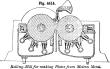
Bessemer's plan, intended to make the plates or sheets of metal directly from fluid iron or steel as it comes from the furnace.
The metal is allowed to flow from the ladle or furnace into the space between two rollers, the said rollers being provided with openings in their centers for the circulation of water.
The external surfaces of the rollers are cooled by jets of water.
The same plan was attempted many years ago by Chance of
Birmingham, England, for making plateglass.
It was abandoned.
[
1968]
 |
|
Rolling-mill for making plates from molten metal. |
Owens's (
Rotherham, England) method of making tires, etc., consists in bending a rod or rods of iron around a block, so as to form a coil having about 1/2 the diameter and 2 1/2 or 3 times the depth of the finished tire.
This is brought in a furnace to a full welding heat, and transferred to a die on the anvil of a steam-hammer, whose piston carries a similar die By these it is compacted into a homogeneous mass, which is expanded to the proper diameter between two rollers, the upper one of which may be lifted to any required distance from the lower by means of a small hydraulic press.
A larger hydraulic press is employed to force the two rolls together in proportion as the diameter of the tire is enlarged.
Other rolls, adjustable by hand or automatically, serve as guides to impart a true circular form to the blank.
Different plans have been adopted by others for preparing tire-blanks for the rolling-machine.
Krupp's method consists in forging a bar of steel into the form of a compressed hoop, which is then cut down the middle, opened out, and afterward finished in the rollers.
Bessemer forms an ingot of steel and cuts out the central part, so that the annulus left may be enlarged by the rolls.
Naylor and
Vickers, of
Sheffield, prepare the circular steel blanks by casting.
An exemplification of the nicety to which the rolling of metal can be carried is shown in the process known as
nature-printing. A piece of delicate lace is placed on a small sheet of metallic tin, which is then passed once between a pair of steel rolls, the surfaces of the latter being brought in close approximation by means of actuating screws.
The pattern of the lace is reproduced with the utmost fidelity on the tin. See nature-printing.
 |
|
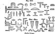
Rolled irons. |
Fig. 4415 exhibits some of the many forms which may be imparted to malleable iron by suitable grooves in the rolls composing the train.
Each is made by one continuous operation.
See also Figs.
2698 and 2699.
Pig-iron is the crude metal from the smelting-furnace, cast into bars or pigs.
The term
bar-iron is restricted to refined or wrought iron.
The bars are
flat, square, round, oval, half oval, or
half round; horseshoe is a fine quality of flat
bar-iron;
nail-rod iron, small square iron of fine quality.
Heavy bands, light bands, and
hoop iron are thin and comparatively wide bars.
Railroad iron includes flat and T rails, axles, fish-plates, bolts, chairs, and spikes.
Building-iron embraces
beams, deck-beams, channelbars, T-iron and fittings.
Angle-iron is known as
equal-sided, unequal-sided, obtuse, star, sash, etc.
Sheet-iron is divided into
common, charcoal, galvanized, and
planished.
Russia sheet is a fine quality of planished charcoal iron.
See Russia iron.
Roofing-iron is corrugated or crimped, and is either
galvanized or
black; it is numbered according to thickness.
Tank and
fire-bed iron are similarly classified.
Boiler-plate iron is thicker than the above, that common in the trade varying from 3/16 to 5/8 inch.
Weights of Wrought-Iron, Steel, Copper, and Brass Plates soft rolled. (Haswell.)
Thickness determined by American Gage.
| No.
of Gage. | Thickness of each Number. | plates, per square foot. |
| | Wrought-Iron. | Steel. | Copper. | Brass. |
| Inch. | Lbs. | Lbs. | Lbs. | Lbs. |
| 0000 | .46 | 18.4575 | 18.7036 | 20.838 | 19.688 |
| 000 | .40964 | 16.4368 | 16.6559 | 18.5567 | 17.5326 |
| 00 | .3648 | 14.6376 | 14.8328 | 16.5254 | 15.6134 |
| 0 | .32486 | 13.0351 | 13.2088 | 14.7162 | 13.904 |
| 1 | .2893 | 11.6082 | 11.7629 | 13.1053 | 12.382 |
| 2 | .25763 | 10.3374 | 10.4752 | 11.6706 | 11.0266 |
| 3 | .22942 | 9.2055 | 9.3283 | 10.3927 | 9.8192 |
| 4 | .20431 | 8.1979 | 8.3073 | 9.2552 | 8.7445 |
| 5 | .18194 | 7.3004 | 7.3977 | 8.2419 | 7.787 |
| 6 | 16202 | 6.5011 | 6.5878 | 7.3395 | 6.9345 |
| 7 | .14428 | 5.7892 | 5.8664 | 6.5359 | 6.1752 |
| 8 | .12849 | 5.1557 | 5.2244 | 5.8206 | 5.4994 |
| 9 | .11443 | 4.5915 | 4.6527 | 5.1837 | 4.8976 |
| 10 | .10189 | 4.0884 | 4.1428 | 4.6156 | 4.3609 |
| 11 | .090742 | 3.641 | 3.6896 | 4.1106 | 3.8838 |
| 12 | .080808 | 3.2424 | 3.2856 | 3.6606 | 3.4586 |
| 13 | .071961 | 2.8874 | 2.9259 | 3.2598 | 3.0799 |
| 14 | .064084 | 2.5714 | 2.6057 | 2.903 | 2.7428 |
| 15 | .057068 | 2.2899 | 2.3204 | 2.5852 | 2.4425 |
| 16 | .05082 | 2.0392 | 2.0664 | 2.3021 | 2.1751 |
| 17 | .045257 | 1.8159 | 1.8402 | 2.0501 | 1.937 |
| 18 | .040303 | 1.6172 | 1.6387 | 1.8257 | 1.725 |
| 19 | .03589 | 1.44 | 1.4593 | 1.6258 | 1.5361 |
| 20 | .031961 | 1.2824 | 1.2995 | 1.4478 | 1.3679 |
| 21 | .028462 | 1.142 | 1.1573 | 1.2893 | 1.2182 |
| 22 | .025347 | 1.017 | 1.0306 | 1.1482 | 1.0849 |
| 23 | .022571 | .9057 | .9177 | 1.0225 | .96604 |
| 24 | .0201 | .8065 | .8173 | .91053 | .86028 |
| 25 | .0179 | .7182 | .7278 | .81087 | .76612 |
| 26 | .01594 | .6396 | .6481 | .72208 | .68223 |
| 27 | .014195 | .5696 | .772 | .64303 | .60755 |
| 28 | .012641 | .5072 | .514 | .57264 | .54103 |
| 29 | .011257 | .4517 | .4577 | .50994 | .4818 |
| 30 | .010025 | .4023 | .4076 | .45413 | .42907 |
| 31 | .008928 | .3582 | .363 | .40444 | .38212 |
| 32 | .00795 | .319 | .3232 | .36014 | .34026 |
| 33 | .00708 | .2841 | .2879 | .32072 | .30302 |
| 34 | .006304 | .2529 | .2563 | .28557 | .26981 |
| 35 | .005614 | .2253 | .2283 | .25431 | .24028 |
| 36 | .005 | .2006 | .2033 | .2265 | .214 |
| 37 | .004453 | .1787 | .181 | .20172 | .19059 |
| 38 | .003965 | .1591 | .1612 | .17961 | .1697 |
| 39 | .003531 | .1417 | .1436 | .15995 | .15113 |
| 40 | .003144 | .1261 | .1278 | .14242 | .13456 |
| Specific gravities | 7.704 | 7.806 | 8.698 | 8.218 |
| Weights of a cubic foot (lbs.). | 481.25 | 487.75 | 543.6 | 513.6 |
| Weights of a cubic inch (lbs.). | .2787 | .2823 | .3146 | .2972 |


