Pro-pel′ler.
A means for the propulsion of vessels.
The varieties may be classed as follows:—
1. Paddle-wheels.
A. On horizontal shaft or shafts.
a. Fixed paddles.
b. Feathering paddles.
a′. Turning on horizontal axes.
b′. Turning on radial axes.
c. Sliding paddles; moving toward and from the paddle-wheel shaft.
d. Paddles attached to traversing chains.
e. Paddles attached to cranks.
f. Collapsing paddies.
g. Paddles in reciprocating frames.
h. Sculling paddles.
i. Cycloidal paddles.
B. On vertical shaft.
2. Hydraulic propeller.
3. Screw-propeller.
4. Rope-traction.
5. Spike-wheel.
6. Pole-propeller.
7. Rack and pinion propeller.
8. Wave-power propulsion.
9. Oars.
10. Sails.
The boats by which the
Roman army under
Claudius Codex were transported into
Sicily were propelled by wheels moved by oxen.
The substitution of paddles for oars is mentioned in many old military treatises.
Thomas Savery, in
England, obtained a patent, in 1696, for a paddle-wheel on each side of a ship, to be turned by means of a capstan.
In the “
Vitruvia de Architectura,” folio,
Como, 1521, there is an engraving of a large vessel propelled by paddles worked by animal power.
A pen-and-ink sketch on an Italian manuscript of the fifteenth century, preserved in the British Museum, shows a vessel propelled by a pair of paddle-wheels on a shaft rotated by gearing and hand-power.
From 1619 to 1662, six patents were granted in
England for devices purposely described with great looseness, for concealment, but which appear to have been paddle-wheels of some kind.
In 1690,
Papin describes “oars fixed to an axis,” a pinion on the latter being engaged by a rack on the piston-rod.
In 1729,
Dr. John Allen patented the hydraulic propeller, forcing water through the stern of the ship at a convenient distance under water.
In 1737, Jonathan Hulls patented a steamboat propelled by a paddle-wheel astern.
In 1738,
David Ramsey obtained a patent in
England for a mode of propulsion of vessels by the force of water ejected by a steam-pump.
In 1780,
Watt suggested the
spiral oar to move canal-boats.
In 1780, the present arrangement of connecting-rod crank and fly-wheel was patented.
In the same year the
Marquis de Jouffroy worked a steamboat 140 feet long on the Saone.
In 1782,
Rumsey propelled a freight-boat on the
Potomac by means of the hydraulic propeller.
A steam-engine worked a vertical pump amidships: the water was drawn in at the bow and expelled through a trunk astern.
In 1785,
Joseph Bramah patented a rotatory engine on a propeller-shaft.
In 1786,
Fitch had a steamboat on the
Delaware, propelled by paddles like those of an Indian canoe.
In 1786,
Benjamin Franklin and
Oliver Evans advocated the hydraulic propeller, receiving the water forward and forcing it out astern.
In 1787,
Patrick Miller patented, in
England, paddle-wheels for propulsion.
In 1788,
Fitch ran his boat by means of reciprocating paddles.
In 1788,
Symington had a steamboat on the lake of Dalswinton, propelled by an engine and side paddle-wheels.
In 1789,
Symington had a boat on the Forth and Clyde Canal, propelled by an engine, and a pair of paddle-wheels placed amidships, respectively fore and aft the engine, and working in a trough extending from stem to stern of the boat, over the keel.
In 1789,
Oliver Evans, of
Philadelphia, had a stern-wheel steamboat which navigated the
Schuylkill.
In 1795, Lord Stanhope invented the “duck-feet paddles,” and ran a boat three miles an hour.
In 1796,
Fitch had a steamboat on Collect Pond, New York, propelled by a screw astern.
In 1802,
Symington's double boat, “
Charlotte Dundas,” was propelled by one middle paddle-wheel abaft the engine and working in the space between the twin boats.
Fulton's and
Bell's steamboats had side paddle-wheels, as also the “
Savannah,” 1819, “Enterprise,” 1825, “Great Western” and “Sirius,” 1838.
The “
Great Britain,” 1843, had a screw, and after this the screw became common.
See paddle-wheel.
The term
propeller is usually applied to the longitudinal revolving shaft with vanes or wings, and more specifically known as the
screw-propeller.
[
1809]
The first use of the propeller was by
Stevens, of
Hoboken, who used twin-bladed screws in 1804.
See screw-propeller.
The bladed screw-propeller was brought forward by
Ericsson in 1836, and the spiral screw in the
dead-wood was patented by
F. P. Smith.
Captain Robert F. Stockton, United States Navy, and
Francis B. Ogden, of
New Jersey, became interested in
Ericsson's invention, and the propeller “
Francis B. Ogden” was launched on the
Thames, and made trips as early as May 28, 1837.
An iron vessel, the “
Robert F. Stockton,” fitted with a screwpro-peller, was launched into the
Mersey, July 7, 1838.
She was the second screw-propeller in
England, as the “
Francis B. Ogden” was the first.
She crossed to the
United States the next year, received an American register, was re-named the “
New Jersey,” and was the first screw-propeller (excepting the small, twin-screw propeller of
Stevens) in American waters.
Ericsson's patent was July 13, 1836, and his propeller had spiral blades, the preferable form.
The first propeller war-steamer was the “
Princeton,” launched into the
Delaware.
Francis P. Smith's name is intimately associated with the introduction of the propeller.
His patent is dated May 31, 1836.
He was the first to make it a continuous screw and to place it in the dead-wood.
His screw was attached to the “
Archimedes” in 1839.
Of the four cigar steamers of
Messrs. Winans, the propeller of the first was placed around amidships; the second, beneath; the third is fitted for trying in various positions; the fourth has a propeller at each end.
In 1863, the “Far-East,” a propeller with two screws, was launched at Millwall,
England.
The screw-propeller generally consists of a
boss fitted upon the end of a propeller-shaft, and with two or more
blades arranged symmetrically around it, so as to balance each other.
The propeller is said to
overhang when it has no after bearing in the
after stern-post or rudder-post.
The propeller may be made to rise out of the water when the ship is under canvas alone.
In this case it is detached from the shaft and drawn up into a
screw-well in the stern of the vessel.
The
pitch of a propeller-screw is the length, measured along the axis, of a complete turn.
The
speed of the propeller means the pitch multiplied by the number of turns in a unit of time; or the speed may be stated in the number of revolutions of the propeller-shaft per minute, where
pitch does not enter into the computation.
The effective
area, or
disk, of a screw-propeller is measured in a thwartship plane, and has for its outer boundary the circle swept by the tips of the blades, and for its inner boundary the outline of the boss.
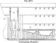 |
|
Unshipping-propeller. |
The
slip of a propeller is the difference between its rate of progression, the length of its pitch to each revolution, and the actual progress of the vessel through the water.
Screw-propellers are known as
adjustable, unshipping, auxiliary, twin or
double, gaining.
Woodcroft introduced the increase-pitch or
gaining-screw propeller; the pitch gradually gaining from the
leading to the
following edge.
When twin-screws are used, one screw is
righthanded and the other
left-handed, so that, being turned in contrary directions in driving ahead, they may counteract each other's tendencies to produce lateral vibration.
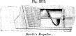
 |
|
Propellers. |
Griffith's had a hollow spherical ball, forming an enlargement of the hub, being substituted for the central portion of the blades.
The blades taper toward the extremities.
The pitch
[
1810]
is alterable, by the rotation of each screw on its stem, which is radial to the main shaft.
Ericsson's blades were on the exterior of a cylinder.
James Montgomery's propeller has a cylindrical rim around the outer edges of the wings, to prevent radial projection of the water and strengthen the wings.
Patented April 12, 1859.
A (
Fig. 3974) shows a section of a three-decked vessel with a screw-propeller.
To disconnect the propeller when the ship is under canvas, it is lifted into a hollow trunk
m constructed over it in the stern of the vessel, entirely out of the water, the outer screw-shaft fitting into a vertical frame of gun-metal which rises along with it. The screw
a is disconnected either by withdrawing the driving-shaft
b out of a socket in the screwshaft, or, which is the better plan, by forming a coupling on the end of the driving-shaft, into which the screw-shaft fits and adjusts itself when slipped down between the guides and trunk.
The screw is then retained in its position by a catch pressed down from above upon the gun-metal frame supporting the bearings, as well as by-its own weight.
The screw is raised into or through the trunk by pulleys and ropes worked by a capstan, the weight of the screw and its shaft being supported by a pawl and rack on each side of the trunk.
In some cases, the screw is only capable of being disconnected from the engines, and left free to revolve by the action of the water upon it, from the motion of the vessel.
Maudslay's substitute is a feathering contrivance, applicable only to two-bladed screws, consisting in placing the blades in a fore-and-aft direction, so that they may lie within the deadwood of the vessel and present little or no projecting surface to impede her progress or affect her steering.
See screw-pro-Peller.
Fowler's steering-propeller (
B,
Fig. 3975) is a submerged wheel turning on a vertical shaft, with paddles which are feathered by an eccentric cam, in such manner that the paddles shall have a pushing and drawing action on the water while passing through the sectors shown by dotted lines, and present only their edges to the water while passing the points
a a, which may be called dead-points so far as their influence in the propulsion of the ship is concerned.
By turning the cam-wheel, which is done by “the man at the wheel” by a simple connection, the feathering is done at different points, and the ship may be backed or turned round and round on her center without reversing the engine.
A propeller of this kind is in use in one of the new torpedoboats of the United States Navy.
Hunter's steering-propeller
C, patented 1874, is similar to the Fowler propeller in some respects.
It has two wheels on opposite sides of the stern-post, revolving in opposite directions.
The blades are feathered so as to have but one dead-point.
Hunter's fish-tail propeller
D consists of a flexible attachment to a post
a at the stern of a ship
The propeller vibrates from side to side with the revolution of the engine.
The leaves of the propeller may be of rubber or thin metallic plates.
The shape the propeller assumes while in motion is shown at
c, and the pressure of first one side and then the other obliquely against the water causes the vessel to advance.
 |
|
Paddle-propellers. |
The hydraulic propeller so often projected — by
Allen, in 1729; Hulls, 1737;
Ramsay, 1738;
Rumsey, 1782;
Franklin and
Evans, 1786 — has been lately revived, the
English government vessel the “Water-Witch” being propelled by a rotary pump taking in water at one end and expelling it at the other.
The vessel is double-ended.
E is a modified form of this propeller.
a a is the passage by which the water enters and leaves the pump-chamber.
Fig. 3976 shows propellers with paddles.
F is a form of propeller whose floats are carried on the ends of levers, which lift them out of the water on the completion of their stroke, at the same time dropping into the water the corresponding set at the other end of the compound lever.
G H are forms of propellers in which the floats are carried on endless chains, which pass over wheels propelled by the engine.
See
Browne's “Treatise on the screw-propeller,”
London, 1867:
Burgh's “Modern screw propulsion,”
London, 1869.
See under the following heads:—
| Archimedean-screw propeller. | Propeller-engine. |
| Auxiliary screw. | Propeller-wheel. |
| Duck's-foot propeller. | Rack and pinion propeller. |
| Elastic propeller. | Rail and traversing-wheel pro- |
| Endless-chain propeller. | peller. |
| Fish-tail propeller. | Reciprocating propeller. |
| Hydraulic propeller. | Rope-traction propeller. |
| Nautilus-propeller. | Screw-propeller. |
| Oar. | Spike-wheel propeller. |
| Oar-propeller. | Traveling-belt propeller. |
| Paddle-wheel. | Wave-power propeller. |
| Pole-propeller. | Windmill-propeller. |