Steam-gage.
(
Steam.) An attachment to a boiler to indicate the pressure of steam.
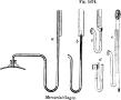
a b c d e, in
Fig. 5674, are forms of mercurial gages; the pressure of the steam rising in the longer leg of the tube is read against the graduated plate.
Fig. 5675 represents piston-gages.
The cylinder has a solid plug, turned and ground, the pressure of
[
2345]
the steam elevating the plug against the force of the spring.
 |
|
Mercurial gages. |
A (
Fig. 5676),
Bourdon gage.
The spring tube is secured at one end and free at the other.
B,
Lane's gage.
The spring is held by the middle, leaving both ends free and pointing upward, so as to prevent water from the siphon which transmits the steam pressure collecting in the tube and freezing in cold weather.
Both ends of the tube are connected by a lever to the index, and vibration of the latter is prevented.
 |
|
Piston-gages. |
C,
Crosby's gage.
The spring-tube is arranged in a manner similar to the last; three connected levers are employed for transmitting motion to the index, and it is claimed that a stronger and heavier tube may be used, obviating danger of straining or bursting under high steampressures.
D,
Allen's gage.
This is a box or diaphragm gage, on the principle of the aneroid barometer.
a is a section through the box, and
b a plan of the diaphragm.
See also pressure-gage; indicator, etc.
Fig. 5677 represents a steam-pressure gage on the principle of the Bourdon barometer (see page 347). The views are respectively a front elevation and a horizontal section, the upper part of the casing being removed.
A series of spiral tubes
a a a communicate at one end with a common opening connected with the steam-chamber, and at the other are joined by a T-piece, which, by means of a connecting-rod, is attached to a lever operating a segment-rack that engages a pinion on the shaft of the index-hand
b, which shows the pressure on a dial.
A second index
c has a projection on its under side, which is struck by the index
b when the steam pressure exceeds a limit to which it has been previously set, carrying it forward till the extreme amount of pressure has been reached; and a ratchet-wheel and pawl prevent it from receding from this point.
A third and shorter index, also controlled by a ratchet and pawl arrangement, is caused to advance a step, and is prevented from returning each time that the limited amount of pressure has been exceeded, so that the gage is caused to register both the maximum pressure and the number of times that the engineer has allowed the pressure to exceed the proper amount.
Fig. 5678 is a view of
Matthews' tube for pressuregages.
It is made without seam, by electrodeposi-tion of metal upon a core of some fusible material, such as stearine or wax. The tube has offsets on one side, in the form of hollow plates.
The lower part is fused to the dial-plate, and has a screw coupling for the steam or carbonic-acid gas pipe.
The effect of elastic pressure in the tube is to press a part the horizontal portions of the offsets and elongate that side of the tube, which becomes bent thereby; the upper end being attached to a short lever or rack, which moves the pointer on the dial.
Shaw's (
Fig. 5679) is also particularly designed to measure the pressure of elastic gases generated by explosive substances.
The pressure from the chamber
a is transmitted through the curved pipe
b, which is partially filled with glycerine, and the perforated disk
c to the foot of the plunger
e, the top of which forms the bottom of a mercurial reservoir; the plunger rising causes a thin column of the fluid to ascend the tube
f, where it is retained by a valve
g until its hight can be conveniently noted.
On partially turning the cock
h, the pressure having been removed, the mercury falls to its normal hight.
In
Fig. 5680, steam pressure acting from within upon the curved metallic diaphragm
a, causes it, through the medium of a series of interposed levers and a segment-rack, to turn the spindle
b, carrying
[
2346]
an index-hand, by which the pressure is indicated on a dial; the mechanism employed gives a much larger amount of motion to the index than that originally imparted to the first of the series of levers by the expansion of the diaphragm.
As the pressure diminishes, the motion of the index is reversed by a spiral spring surrounding its shaft.
 |
|
Differential piston pressure-gage. |
 |
|
Diaphragm pressure-gage. |
In
Fig. 5681, the steam admitted within the box of the gage expands its elastic corrugated top, forcing up a rod, which, through interposed mechanism, moves the dial index.
As the pressure falls, the course of the index is reversed by a conical spiral spring, which reverses the movement of the rod.
 |
|
Diaphragm pressure-gage. |
 |
|
Duplicate tube pressure-gage. |
In
Fig. 5682, the two tubes
a b have a common base, to which steam is admitted, and their free ends are connected by a flat, bent spring.
A link and rod, centrally connected to the spring, actuate the segment-rack, which gears with a pinion on the index-shaft in the usual manner.
Edson's recording steam-gage (
Fig. 5683) consists of a case, secured by a lock and key, and having several connected air and steam tight drums
a a a of thin flexible metal.
A rod
b on the upper one of these is attached to a segment which directly, or through intermediate gearing, actuates a rack-bar provided with a pawl, which rotates the cylinder
c to the right, causing it to take up some of the paper from the cylinder
d, on which a roll is wound, as the gage is expanded by steam from the boiler entering the apparatus through a pipe
e in the bottom compartment.
An opposite pawl prevents the paper-carrying cylinders from turning backward as the boxes
a a a collapse under a diminished pressure of steam.
By means of suitable gearing the arm
f, carrying a pencil or tracing-point at its lower extremity, is caused to rise and fall, impressing a zigzag line on the paper as the steam pressure varies.
By means of clockwork mechanism, actuated by the engine or otherwise, the motion of the cylinders
c d may be made uniform and continuous, so as to leave a permanent record of the variations of pressure for 12, 24, or a greater number of hours, the paper having been previously ruled with a system of horizontal lines indicating the pressure in pounds and vertical lines for the hours.
A scale and pointer
g enable the pressure at any moment to be more readily ascertained by inspection.
The handle of the inlet steam-cock enters the gage, and is so secured that it cannot be withdrawn until the gage-door is unlocked, thus preventing tampering with the record.
 |
|
Edson's recording steam-gage. |


