Ri′fle.
1. (
Fire-arms.) A fire-arm having the bore spirally grooved, so as to impart a rotary motion to the bullet and cause it to keep one point constantly in front during its flight.
Grooved-bored small-arms are said to have been in use as far back as 1498; these, however, do not seem to have been rifled in the proper acceptation of the term, the grooves being straight and intended merely to prevent fouling of the bore and facilitate cleaning.
The grooves were made spiral by Koster of
Birmingham, England, about 1620.
In
Berlin is a rifled cannon of 1664, with 13 grooves, and one in
Munich of perhaps equal antiquity has 8 grooves.
The French Carabineers had rifled arms in 1692.
Pere Daniel, who wrote in 1693, mentions rifling the barrels of small-arms, and the practice was apparently well known at that time.
Rifles were early used by the
American settlers in their conflicts with the Indians; and their first successful employment in civilized warfare is said to have been by the colonists in the war of the Revolution.
In the
Artillery Museum at
Paris is a large assortment of old rifles, comprehending a great diversity of grooves and twists.
These exhibit straight grooves and grooves of uniform twist.
In some the twist commences near the breech; in others, at the middle of the barrel or toward the muzzle.
In some specimens, the grooves make from 1 1/2 to 2 turns in the length of the barrel; nearly two thirds have an even number of grooves, and
[
1940]
about three fourths upward of 6 grooves, varying from 7 to 12.
Nearly seven eighths have grooves with rounded edges.
Much the greater part of the remainder have triangular, but a few have rectangular grooves.
None have grooves decreasing in depth from the breech toward the muzzle.
This species of groove was introduced by Tamisier, in 1846, but is now general among the shallow-grooved arms intended for discharging expanding bullets.
Tamisier also introduced the plan of increasing the twist of the grooves as they approached the muzzle.
With the earlier rifles and until a very recent period, a patch was generally used over the ball, causing it to fit tightly in the bore and take hold of the grooves.
This was a somewhat precarious method; and, accordingly, the
Brunswick rifle, one of the latest specially adapted for the round ball, was made with but two grooves, into which an annular rib on the ball fitted, compelling it to follow these.
Lancaster effected the rotation of the ball by making it and the bore of the gun slightly elliptical in section.
To this succeeded the system invented by Delvigne, and improved by Thouvenet, Tamisier, and Minie, in which an elongated bullet, fitting loosely in the bore, is expanded, so as to fill the grooves.
This permitted greater rapidity in loading, and insured the rotation of the projectile.
See bullet, page 401.
Rifling is now generally adopted in small-arms.
The number of grooves is usually three.
They are made very shallow, and gradually diminish in depth from the breech to the muzzle.
The Swiss Federal rifle, introduced in 1848 by
Colonel Wurstemburger, has eight grooves with a twist of one turn in three feet. In this the bullet is not expanded, and it has enjoyed a high reputation for accuracy.
The caliber is small, 41 inch, the bullet weighing 257 grains, and the powder charge 62 grains.
The plan of having studs or ridges on the bullet to engage the grooves has not been extensively adopted for smallarms.
The rifle of
General Jacobs,
East India service, employs a bullet of this class, having four ridges corresponding to the four grooves of the rifle, and used with a patch.
In
Murphy's mode, the rifling only extends four inches from the muzzle, and has its pitch lefthand-ed to correct the slight tendency to pull the gun over to the right in pulling the trigger.
The
Whitworth rifle has a hexagonal bore; the
Westley Richards carbine, an octagonal bore; the
Lancaster carbine, an elliptical bore, or it may be described as a spiral of oval section.
The rifling of gun-barrels in the
Remington Works at
Ilion, N. Y., is done by a very small cold steel chisel inserted in a long rod firmly attached to a rapidly revolving wheel, which also moves up and down a platform.
The barrel is run over this rod and placed firmly in position.
As the wheel revolves, the chisel in the rod cuts the rifling in the barrel; and as the wheel advances and retires very rapidly, the twist of the rifling is very elongated.
In breech-loading arms the bullet is of slightly larger diameter than the bore measured from land to land, and
slugs so as to fill them when driven forward by the ignition of the charge.
See list of breech-loading fire-arms on pages 855– 862, and illustrations, Plates XVI., XVII., XVIII.
See also bullet.
Sharps' is one of the very oldest successful guns of the breech-loading class, and the first in which a vertically sliding breech-block was employed.
Originally, a paper cartridge was used, the rear end of which was cut off by the sharp forward end of the breech-block in its upward movement; a cartridge having its end closed by a thin combustible paper
was subsequently substituted for this.
At present the metallic cartridge is employed.
In
Fig. 4324,
A is a vertical section of the gun, the parts in loading position;
B, the parts in firing position;
C, a top view;
D, a transverse section, with the breech-block down;
E, front view of the breech-block, showing in the center the end of the firing-pin, and at the right-hand side the groove occupied by the cartridge-retractor shown by two views at
G H. F is a metallic cartridge in section.
a is the metallic breech-piece, secured to the wooden stock
b, and into which the barrel
c screws;
d is the breech-block, connected by a toggle
e to the guard-lever
f, and having a vertical movement
[
1941]
within a slot in the breech-piece
a. The upper surface of the breech-block has a groove
a′ in line with the barrel, serving as a guide for the insertion of the cartridge into the chamber
g when the breech-block is depressed out of the way. This is effected by throwing down the guard-lever
f, as shown at
A. The cartridge is then inserted, and the guard-lever brought back to the position shown in
B, the hammer
h having been previously set at half-cock.
On depressing the lever the firing-bolt
i is automatically moved rearward by a spur on its forward end, so as to clear the point of the bolt from the cartridge shell and rear end of the barrel.
The shell is retracted by the same movement.
In order to fire, the hammer is set at full cock, and on pulling the trigger, its face comes in contact with the end of the firing-bolt, which is thrown forward, its end impinging against the base of the cartridge where the capsule containing the fulminate is placed.
The firing-bolt is so adjusted that the hammer cannot come in contact with it until the breech is perfectly closed, thus affording a security against premature discharge.
The cartridge shells may be used a number of times.
The exploded cap is removed, the shell cleansed, a new cap inserted, a charge of powder poured in, over which is placed a paper wad, and a lubricating wad composed of 1/3 beeswax and 2/3
sperm oil, and the bullet pressed home with a ball-seater.
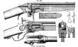
Among the best known and most efficient arms of its class is the revolving-rifle of the late
Colonel Samuel Colt, who, by the simplicity and ingenuity of his devices and his unceasing care to insure perfection of workmanship and material, first rendered the revolving system a success, and succeeded in producing a weapon which is known and used throughout the world.
In 1830,
Colt invented a device “for combining a number of long barrels so as to rotate upon a spindle by the act of cocking the hammer.”
His improvement on this plan, which consisted in using a rotating cylinder containing several chambers, all of which discharge through one barrel, was patented in
England in 1835, and in this country in 1836.
The rifle (
A B C,
Fig. 4292, page 1929) has a steel barrel with seven flat angular grooves.
The lockframe is provided with a bridge
a above the barrel, and the stock is in two parts
b b′, called respectively the butt and tip. It is adapted to receive a bayonet.
The tip in some cases is dispensed with.
The rod by which the cylinder is secured to the barrel has a ratcheted disk
c′ near its rear end, which is engaged in the act of cocking, by a hook connected with the tumbler, rotating the cylinder and bringing each chamber successively in line with the barrel.
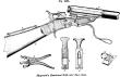
Fig. 4325 shows
Maynard's rifle.
It may, at the option of the user, be provided with two rifle-barrels of different calibers and a shot-barrel, one of which may be substituted for the other by simply releasing the pin
a which, with the fixed pin
b, connects the barrel with the stock and firing mechanism, removing the first barrel and securing the second by placing the pin
b in the hook and reinserting the pin
a after bringing the holes in the flanges, one of which is seen at
c, and the arm
d (shown in dotted lines) into line.
These operations take but very few moments to perform.
The rear end of the barrel is thrown up for this purpose, and also for loading, by turning forward the lever
e, which also serves as the trigger-guard.
When this is restored to its normal position, it is held by the pin
f near the small of the stock, and the movement, by means of the arm
d, draws the breech down into a groove in the metallic part of the stock, where it is in position for firing.
Either the forward or backward movement of the trigger-guard
e places the lock at half-cock, obviating the danger of premature discharge.
The
Maynard rifle was perhaps the first in which a metallic cartridge was employed.
The report of
Major Bell to
Colonel Craig,
Chief of Ordnance, United States Army, May 16, 1856, describes the firing of
Dr. E. Maynard's rifle, charged with a metallic cylindrical water-proof cartridge, and dwells upon the important fact of the coincidence of the axes of the ball and the barrel, obtained by the symmetrical setting of the ball in the metallic shell.
The bullet was held in the shell by its exact fit, and without choking the shell upon it. The
Maynard coilprimer was then used with it; the nipple and percussion-cap were substituted in 1864; the plunger exploder, in 1873; the Berdan primer, in 1874.
The cartridge cases
g are of sheet-metal, sufficiently thick to permit their being used an indefinite number of times, and have a thick base, perforated to allow the passage of fire from the primer, which is a cap placed on a nipple slightly recessed within the cavity
g′ of the base.
The charge of powder is placed within the case, and with the wad, if one be used, is rammed by the short rod
h, which also serves for ramming the wad over shot when these are employed.
If ball be used, it is pushed into the case by means of the loader
i, which has a cylindrical cavity terminating in a hollow conoid fitting the point of the ball and keeping it in truly axial position in the case.
The flange at the base of the cartridge enables it to be readily withdrawn from the loader and from the barrel after firing.
The device
k is used for pressing the primer, a shallow, flanged cap, upon the nipple.
The cartridge, having been loaded as described, is pushed into the rear of the barrel, which is then depressed by throwing backward the triggerguard
e until its loop rests against the stock, the pin
f entering a hole in the guard.
The hammer
l is drawn back to full cock, and on pulling the trigger the main-spring throws the tumbler forward, causing the hammer to strike the firing-pin
m, which is projected forward within an aperture in the breech-block
n, and explodes the primer.
The breech-block, backed by the stock in rear of it, sustains the force of the recoil.
 |
|
Maynard's combined rifle and shot-gun. |
The rear sight
o, pivoted on the small of the stock, is a slide-sight, adapted for long ranges, and is turned down when not in use. The blocksight
p is used for short distances.
The front sight
q is compound, consisting of an ordinary sight and a globesight
q′ turning on a common pivot in a slotted base fixed near the muzzle of the barrel.
The barrel being readily detachable, enables the whole arm to be packed within a space not exceeding the length of the barrel, usually 26 inches.
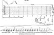
Fig. 4326 shows a plan of the rifle-grounds at
Creedmoor,
Long Island, and
Fig. 4327 is a sketch of the group of marksmen.
The figures on the plan give the distances of the different ranges, and the lower view shows the mode of shooting, which was singular enough with
[
1942]
some of the party.
One man has the toe of his boot for a rest, another his crossed legs.
The shooting at the contest between the
American and the Irish teams was the best on record.
| The possible individual score was | 180 |
| The possible six-team score was (6 × 180) | 1,080 |
| The best individual score (Fulton, American) was | 168 |
| The American team score was | 934 |
| The Irish team score was | 931 |
The best previous shooting at Wimbledon was 1,204 out of a possible 1,440.
Rifled cannon were first successfully employed expansible cups or envelopes of soft metal, which are forced into the grooves in the act of firing, so as to prevent windage; as
Parrott's,
Blakeley's, etc.
4. Breech-loading guns.
In these the projectile has a soft metal coating, which is forced into the grooves in the same way as the leaden bullets of small-arms;
e. g. the Prussian and Armstrong's.
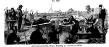
The grooves of the
Armstrong muzzle-loader are made deeper on one side than on the other, as shown in
Fig. 4328,
a; the deeper part is of uniform depth and connected with the shallower during the Franco-
Austrian war in
Italy, 1859.
The
Lancaster gun had, however, been tried to some extent during the Crimean war.
They may be divided into four classes:—
1. Guns in which the projectile is made entirely of hard metal, and of section corresponding to and fitting the bore, but having a small windage; such as the
Lancaster and
Whitworth, just described.
2. Muzzle-loading guns with balls having studs or ribs fitting the grooves; as the
Armstrong and others.
 |
|
American and Irish teams shooting at Creedmoor (1874). |
3. Muzzle-loading guns having projectiles with part by an incline.
The studs on the shot are only half the width of the grooves, and of hight sufficient to allow the shot to enter the bore and pass down freely to its seat, as shown at
b. When driven forward by the force of the discharge, the studs come in contact with the incline, and are
shunted over into the shallower part of the groove, against which they bear firmly, causing the shot to leave the bore in a line concentric with its axis, as shown at
c.
In the
Scott gun this is effected by making the
[
1943]
grooves of gradually decreasing depth from one side to the other (
d).
The French system, of which the Woolwich is a modification, is shown at
c.
The
Austrian (
f) in principle resembles this, the grooves being a series of spiral triangles; the projectile (
g) has corresponding soft-metal ribs, which readily pass down the bore along the deeper sides of the grooves and are shunted over to the shallower sides when discharged.
See also shell; bullet; and specific indexes under ordnance and projectiles.
2. (
Husbandry.) A strop with a surface of emery for whetting scythes, etc.
 |
|
Rifling and rifle projectiles. |