Plan′ing-ma-chine′.
1. (
Wood.) A machine for truing up and facing boards or the sides of timbers.
When it also works the edges, it is known also as an
edger; when the edges are respectively tongued and grooved, they are known as
matched, are said to be
matched up; when the stuff is molded or dressed to ornamental shape, the machine is known as a molding-machine (which see).
Planing-machines for wood-working are of three general kinds, and will be mentioned in the order of their invention, not of their usefulness.
a. The
reciprocating planing-machine was invented by
General Bentham in 1791, its action being based upon that of an ordinary plane.
It had a large plane or stock with inclined bits (plane-irons) which reciprocated on ways, planing down to a thickness the board which lay upon the bed beneath, the board being moved forward after each reciprocation of the plane, in order to expose a fresh surface to be worked.
The plane-iron was the whole width of the board, and slips on the bed determined the depth of penetration.
The plane was moved to and fro by a crank; it was held down to its work by weights, and was lifted above its work during the back stroke, to save the dulling of the cutter.
The
scaleboard plane is of this character, and is used in cutting from boards or balks the wide chips used in making some descriptions of boxes, for veneer, and for other purposes.
It has a plane-iron the width of the board, and the protrusion of the iron from the sole of the plane determines the thickness of the scale.
General Samuel Bentham's name is preeminent in the history of machines for working wood.
See wood-working machines.
This plan has been again and again tried, but has not succeeded.
It was probably the feature of
Hatton's planingma-chine, English patent, 1776.
It appears that subsequently
General Bentham (brother of Jeremy) made molding-machines with rotary cutters, and also
planing-machines to dress both sides at once.
b. The
transverse planning-machine was invented and patented by Bramah, in 1802.
It has a horizontal roughing-wheel armed with gouges, followed by plane-irons for finishing.
It is known also by the name of the
Daniels planing-machine.
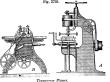 |
|
Transverse planer. |
A,
Fig. 3795, is a view of a machine of this kind by
Richards of
Philadelphia.
As shown, it is especially adapted for pattern and car shops; is wholly of metal, including the carriage, which is planed true, moves on anti-friction rollers, and is provided with end and side clamps that will hold pieces 15 inches wide, 6 inches thick, and 6 or more feet in length, or as small as 1 inch square.
See also transverse planer.
The clamps and all the adjustments are so arranged as to be instantly changed for pieces of various sizes.
The feeding movement is performed by hand.
This admits of a rapid manipulation of the machine, modifies the feed to suit the work, and allows the operator to feel the action of the cutters.
The driv-
[
1729]
ing-pulleys can be arranged so that the machine will stand either parallel with or transverse to the line-shaft; a countershaft being required in the first case.
The cutter-head is of wrought-iron, the spindle of steel, and the bearings of brass.
The framing, being open on the front, gives easy access to the cutters, and admits pieces of any width.
The operator is protected by an iron shield in front of the cutters.
In Bramah's machine, as used in the gun-carriage department of Woolwich Arsenal,
England, the boards passed beneath a disk-wheel which rotated on a vertical spindle, and had 28 gouges and 2 plane-irons on its lower face.
The lumber traversed on either of two beds, one on each side of the spindle, the feed being by means of a continuous chain which passed over pulleys at the ends of the tracks.
The cutter-wheel was large, and revolved 90 times in a minute.
Fig. 3795 is a view of the Daniels
planing-machine, made by
Fay & Co.,
Cincinnati, Ohio Instead of the wheel with 28 gouges and 2 double-irons of the original
Bramah, it has a pair of arms, each carrying a cutter.
The timber to be dressed is dogged to a sliding carriage, the feed being automatic and adjustable as to rate.
The cutter is driven by a band upon the roller on the vertical shaft of the cutter; this portion of the machine being in a gate, which has a vertical adjustment in the standards of the frame, so as to determine the level on which the cutter shall work.
c. the
cylinder planing-machine. This is now the usual machine.
It has cutters on a drum rotating on a horizontal axis over the board which passes beneath.
The cutter-drum is the width of the board, and may be repeated underneath and at the edges, so as to plane top, bottom, and edges simultaneously.
In some cases, the board travels on its edge.
An early form of this was
Muir's planingmachine for facing flooring-boards.
It had rotary cutters above and below, two oblique fixed cutters to smooth the faces, two cutters to make the sides parallel, and two others to make the rabbets which form a tongue.
The
Woodworth planing-machine, patented in 1828 and twice extended, became an odious monopoly, and did much to discredit the patent system.
It claimed the combination of cutting-cylinders and feeding-rolls.
Cutting-cylinders were used by
Bentham thirty-five years before, and rollers for feeding lumber to circular saws were described in
Hammond's English patent, 1811.
Richards's roller-feeding
planing-machine (
B,
Fig. 3795) is a small machine of the cylinder class, adapted for preparing lumber for pattern-makers and others.
As shown, it is constructed to plane from 1/8 to 5 inches thick and 20 inches wide; has a wrought-iron cutting-cylinder, wrought-iron feeding-rollers, and cylinder-bearings of brass.
 |
|
Revolving-cylinder wood-planing machine. |
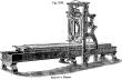
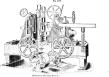
The
planing-machine (
Fig. 3797) may be taken as an example of its class.
It has an
iron frame, will plane 24 inches wide, and match up to 12 inches. It has a three-knife steel-lipped cylinder for facing, and triple-sided gun-metal matcher-heads.
It planes up to 4 inches thick.
This form of
planing-machine, with peculiarly shaped cutters, constitutes a molding-machine (which see).
The
outside molding-machine is one in which the head overhangs the bearing.
The
inside molding-machine has its cutter-head between bearings.
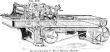
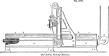
 |
|
Dimension planing-machine. |
Fig. 3798 is a view of
Richards's
planing-machine for dressing to shape and dimensions, timbers for cars, machines, bridges, etc. It planes true and out of wind three sides at a time, the working side being previously dressed to lie upon the carriage of the machine.
It has a cross cylinder-cutter for the top, and two vertical cutters for the sides, with in and out adjustment for the latter and up and down adjustment for the former, so as to dress to any size within the dimensions for which it is constructed.
2. (
Metal-working.) A machine in which a metallic object dogged to a traversing-table is moved against a relatively fixed cutter.
In practice, the cutter is adjusted in a stock, and is usually fed automatically between strokes.
The earliest machine for planing metal was invented by
Joseph Moxon, and described and illustrated at pages 208 and 215 in “Mechanick Exercises, or the Doctrine of Handy Works,” published in
London, 1694.
the metal-
planing machine was subsequent to the lathe, and would appear by this invention to have grown out of it.
The machine was employed for planing brass moldings, and consisted of a revolving cutter and an adjustable guide or table, along which the bar or brass to be planed was drawn by the operator.
The machine appears to have been entirely successful for the purpose intended.
This was the original
milling-machine.
As in the case of so many important inventions, however, but little, progress was made for a while, and the original invention and inventor were almost forgotten, when, nearly a century after
Moxon, the necessities of the times caused the revival of the invention to be made with special ref-
[
1730]
erence to iron.
In the year 1751, the engineer of the Marly Water-Works on the
Seine, France, contrived and put in execution a machine for planing out the wrought-iron pump-barrels employed in that work.
(See page 454, plate 45, in
Buchanan's “Practical essays,” published 1841.) This is believed to have been the first instance in which iron was reduced to a plane surface without chipping or filing.
The present metal-
planing machine is an application of the slide-rest, which was invented by
General Sir Samuel Bentham and described in his patent of 1793.
The
planing-machine dispensed, to a great extent, with chipping and filing, and is at the bottom of all successful fitting of machinery.
It is next in importance to the lathe, and has, since its invention, about 1814, been much modified and improved.
Its use has effected a complete change in the manufacture of tools and machinery of every class, and has made possible the construction of many works which could hardly otherwise have been attempted.
In its invention we find credits to
Clements of
London, who was a workman in Bramah's shop; to
Fox of
Derby, and to
Roberts and
Rennie of
Manchester.
Bramah, it appears, employed, in 1811, the revolving cutter to plane iron, thus adapting to metal the form found best adapted to wood-working, and which survives in our
milling-machines, now so much and deservedly esteemed.
Clement, previous to 1820, made a
planing-machine for planing the sides of looms and the triangular bars of lathes.
The bed moved on rollers, and the tools cut both ways.
Much of the moved on rollers, and the tools cut both ways.
Much of the work for
Babbage's calculating-machine was planed on
Clement's machines.
Fox made a
planing-machine, in 1821, to plane the cast and wrought iron bars used in lace-machines.
It planed 10 feet 6 inches, 22 inches in width, on an object not above 12 inches high.
Rennie, in 1820, it appears, had a planingmachine with a movable bed urged by an endless screw and rack and with a revolving tool.
The first machines were moved by a chain winding on a drum; rack and pinion, and eventually the screw arrangement, were substituted.
The metal-
planing machine of
Joseph Clement of
London is illustrated and described on page 157
et seq., Vol.
XLIX., “Report of Society of Arts” for the year 1832.
The inventor, in his communication to the society, says that he aimed to do with this machine for straight surfaces all that the lathe was made to do for round surfaces.
The paring or cutting tool and the stuff to be operated upon were held respectively, as in the lathe, at fixed relative distances from each other, entirely independent of any mouth-piece, such as employed in the plane proper or carpenter's plane.
This great invent on included the reciprocating bed, guided and moved horizontally and automatically with a greater or less stroke.
It included two cutters, capable of being directed forward and backward and at different elevations, so as to cut at both forward and backward strokes of the bed.
The cutter or cutters were fixed in a slide-head, and by suitable guides, screws, and mechanical connection with the bed, were shifted automatically at the end of every stroke, and could be fed downward at will, so as to make a deeper or shallower cut.
The cutters could be canted to one or other side to any angle whatever, so as to plane either the right or left side of the stuff.
In a word, it was the
planing-machine of our day.
Clement was a worthy pupil of the illustrious
Joseph Bramah.
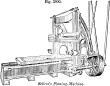
 |
|
Self-acting planing-machine. |
Fig. 3799 is a side elevation of a self-acting
planing-machine for horizontal, vertical, and angular planing.
a, bed and standards.
b, guide-screw.
c, the table, having a nut (not shown) taking into the guide-screw, by which it is moved along the bed.
d, the driving-apparatus, which, by being at the end of the bed, is out of the workman's way.
e, uprights.
f, cross-slide.
g, reversing-tool to plane both ways.
h h, two stops, which can be fixed at any distance apart, according to the desired traverse of the table.
j, lever upon which the stops
h act.
k, rod and strap lever, by which the driving-strap is shifted from one pulley to another, and the direction in which the table
c moves is changed.
l, band-pulleys which transmit the motion of the lever
j to the reversing-tool at the same time as the strap is shifted, and the tool is thus made to turn at each end of the work.
The band-pulleys also impart self-acting motions to the tool in the transverse, vertical, and angular directions, as required.
The reciprocation of the supplementary tool-frame at right angles to the motion of the table gives the transverse cut. The angular cut is given by the combination of the motions, transverse and longitudinal.
The same general arrangement of machine with a fixed tool, to plane only one way, and the driving-apparatus
d, constructed to give to the table a quick return-motion, is sometimes made.
The tables of machines which do not plane above two feet long are moved by a crank.
Planing-machines were farther improved by the use of two tool-boxes on the cross-slide, and by the application of sliderests or tool-boxes fixed upon the uprights, self-acting vertically, for planing articles at right angles to the tools on the cross-slide.
The necessities of the manufacture of wrought-iron and steel ordnance, and the revolution they have caused in the construction of vessels of war, have called into requisition a great many alterations and adaptations of the present machines, as well as many entirely new ones.
The
planing-machine especially has been called upon to plane the edges of armor-plates to different curves, shapes, or angles.
In most cases, this has been accomplished by a pattern-bar of iron or steel, placed on edge in a small chuck fixed upon the surface of the table, adjustable by set-screws, and shaped to the form to which it is required to plane the edge of the plate; as the table travels, this bar, which runs between two circular rollers attached to the under side of the cross-slide, moves the tool sideways, according to the amount of curve in the shaper or guide-bar, the tool-box being disconnected for this purpose from the screw in the cross-slide.
Fletcher's duplex
planing-machine (
English) is arranged with double beds and double tables, each table having a separate set of gearing, with starting, stopping, and feed motion.
There are two tool-boxes on the cross-slide, each of which is independently self-acting, so as to work with its own table.
Thus, the two tables may be used separately as two smaller machines working independently of each other, and capable of planing different lengths of work at the same time; or, when planing a large article, the two tables, gearing and motion, may be coupled, so as to form one large machine,—an arrangement rendering the machine capable of doing a variety of work.
Also, one table may be fixed stationary as a bed-plate to bolt awkwardly shaped or long pieces of work upon, while they are planed by a sliderest fixed upon the other table.
When used as one machine both sets of straps and gearing are in operation, and are reversed by the stops of one table only, so as to ensure the straps moving at the same time.
This machine is capable of planing articles 10 feet wide and 10 feet high.
The racks on the under side of the tables are 3 inches pitch, with stepped teeth; the wheel working into the rack is 3 feet 9 inches diameter at the pitch-line, and is driven by a smaller pinion.
By this arrangement a steadier motion is obtained; and also the pulleys and driving-gear can be placed entirely behind the face of the uprights, so as to leave the front of the machine perfectly clear, that the straps may not be in the way when putting the work on and off. The pulleys, being below the ground-line, may be driven by a horizontal underground shaft at the back of the machine, and no straps will then be visible.
Machines of this description are made with beds 40 feet long, to plane work up to 14 feet in width.
Fig. 3800 is a perspective view of
Sellers's selfacting planingmachine for horizontal, vertical, and angular planing of any required length, with spiral-gear driving-motion; positive geared feeds, self-acting in all directions, with tool-lifter operating at all angles, and improved beltshift-er.
This machine stands parallel with the overhead drivingshaft; the bed and table are fitted to uniform gages, so that the table will work with either end toward the uprights, or on any bed of the same size machine.
Among the modifications of the
planing-machine adapted for quick work, for cutting grooves and what
[
1731]
not, may be cited the
jack, jim-crow, key-groove machine, milling-machine, planer-bar, shaping-machine, slotting-machine.
The
jack is a small machine, and is named from its quick, handy ways and its compact form.
The
jim-crow is the improvement of
Joseph Whitworth upon the Clement
planing-machine.
It has a reversing-tool to plane during both motions of the bed, and is named from its peculiar motion, being adapted to “wheel about and turn about, and do just so.”
The table is moved endways by a quickthreaded screw, which allows the driving motion to be placed at the end.
Whitworth's English patent is No. 6850, of December 11, 1835.
The
key-grooving machine is a modification invented by
Robert Roberts of
Manchester.
It has a strong mortise-chisel, which is reciprocated vertically by an eccentric, while the wheel to be slotted is laid horizontally on a slide, and traversed toward the cutter until the slot has attained the depth required.
The
milling-machine is one in which the work is dogged to a table and fed toward a revolving cutter, which has a serrated face which cuts away the metal.
See milling-machine.
The
planer-bar is a form in which the tool is on the end of a bar, which penetrates the interior of an object, and thus is enabled to reach deep-seated places.
See shaper-bar. See also
Fig. 3787.
The
shaping-machine is one in which the object is chucked on an axis or mandrel, the tool traversed above the work in a line parallel with the axis of the mandrel; the latter, being slightly rotated between each stroke, constitutes the feed, and the result is a circular shape attained by straight cuts.
See shaping-machine.
The
slotting-machine — or
paring-machine, as it is sometimes called in
England — is a substitute for the file in hollowing out objects, and thus resembles the
key-grooving machine; but the slotting-machine has two horizontal slides at right angles to each other and a circular adjustment or turn-plate, all three used in shifting the position of the work below the vertically reciprocating cutter, and all three having devices for mechanically
feeding the cut, as it is called, or for moving the slides between each stroke.
The
crank-planer is a shaping-machine for metal, in which the tool-stock is reciprocated by pitman attachment to a wrist on a crank.